Inclined Planes
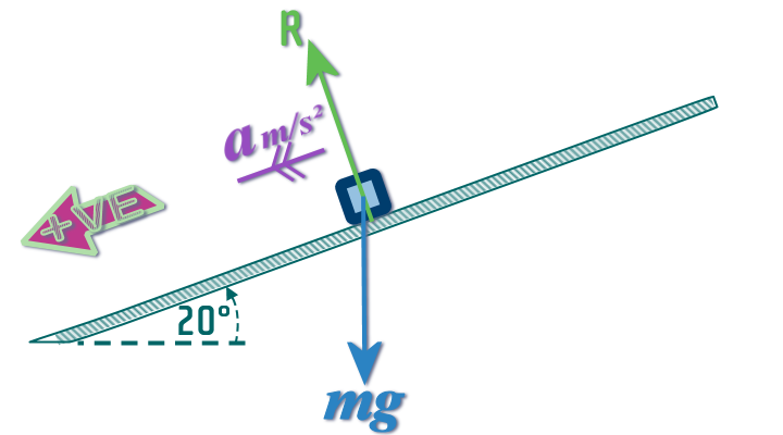
In we have a particle on a smooth slope then at least TWO forces will be acting on it:
- Its weight (acting vertically downwards)
- The reaction force of the surface (acting at 90° to the surface - so therefore, NOT vertically up!!!)
So, our diagram might ╔═►
look like this ═════╝
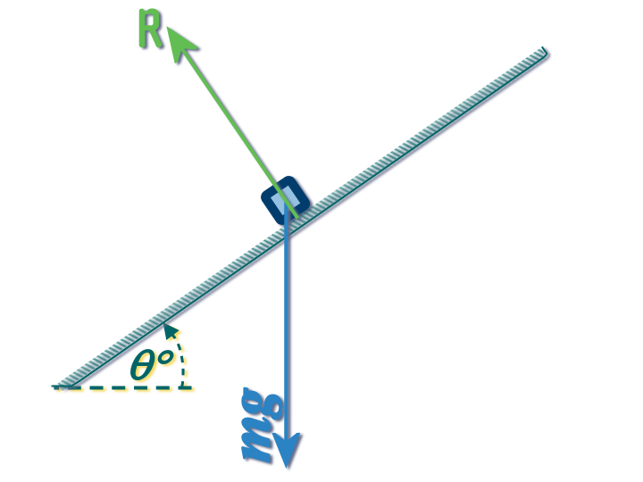
On a smooth slope, the particle will accelerate down the slope (on a rough slope, the friction might be sufficient to hold it in place)
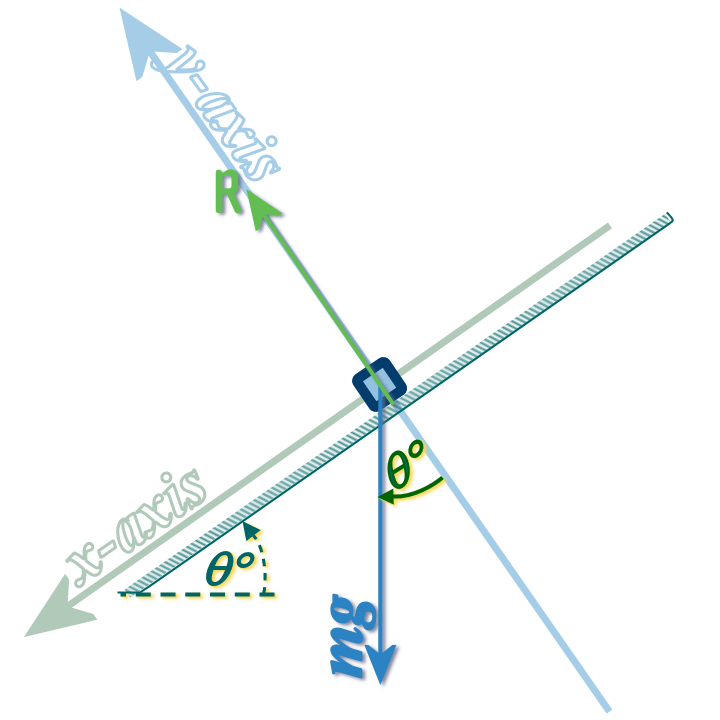
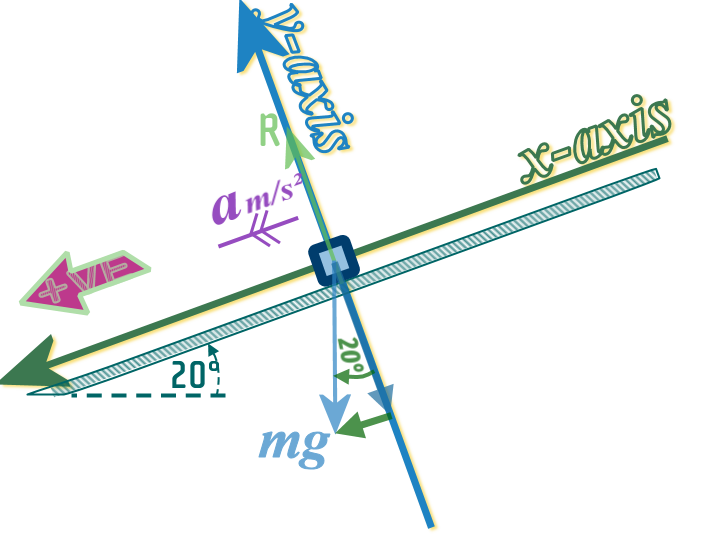
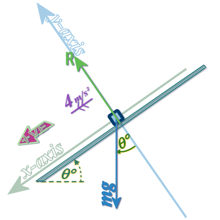
Step 1: Adding in our axes:

Step 2: Finding Oblique Angles
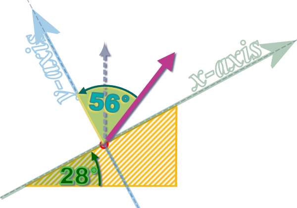
Since the \(x\) axis is now along the slope (and no longer horizontal) it now makes an angle \(\theta \) with the horizontal...
The first thing we should realise is that:
If the \(x\) axis is at an angle of \(\theta \) to the horizontal, then the \(y\)-axis must be at an angle \(\theta \) to the vertical! N.S.S 😲
├────────────┬────────────┐
│ │
│ ??
│
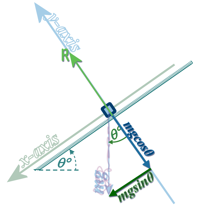
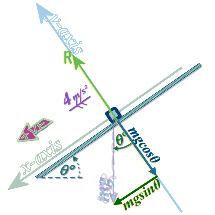
▼Step 3: Resolving Oblique Forces
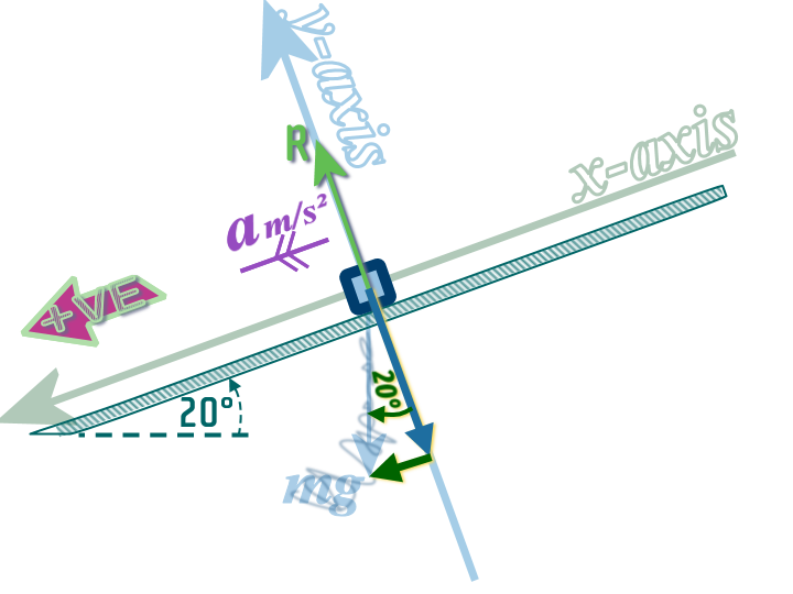
Then, since the 'weight' is not parallel to the axes, we have resolve it into a component parallel to the \(x\)-axis and another component, parallel to the \(y\)-axis
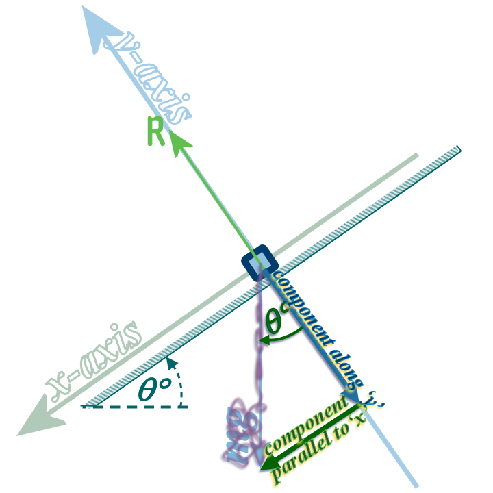
We can then just use simple trigonometry to find the numerical values of these components
These components replace the original force; so you must gently cross out the original weight force:
We don't NOT need it no more!
Finding the Acceleration
Now that we can resolve the forces, we can find the acceleration as we did before, using F = ma:
Dynamics:
Define a +VE Direction:
Usually, the direction in which the particle about to move, or already moving
If there are any forces in the perpendicular direction, then apply
forces UP = forces DOWN
In the parallel direction, apply
(+VE forces) - (-VE forces) = ma
Applying Dynamics Parallel to \(x\):
\[\begin{align} \left( +VE\,forces \right) \,&-\,\left( -VE\,forces \right) \,&=\,ma\\\left( mg\sin \theta \right)\, &- \,\left( 0 \right) \,&=\,ma\\&g\sin \theta \;\;\;&=\,a\end{align}\]
▪
▪
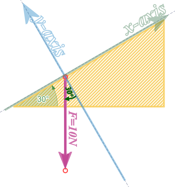
Question 1, part (a): We need to break \(10\) N force (acting downwards, like a weight would...) into components that are parallel to and perpendicular to the slope...
Which means we place our \(x\)-axis along the surface (i.e. slope), and our \(y\)-axis perpendicular to the surface, like this:
The next thing to do is to find the ANGLE between the \(10\) N force and one of our axes (either one...)
This rule will be helpful:
If the \(x\) axis is at \(\theta°\) to the horizontal, then the \(y\) axis will be at \(\theta°\) to the vertical
😊
Now, we need to move from the start of the arrow (representing the \(10\) N force)  ...
...
...to the end of the arrow  :
:
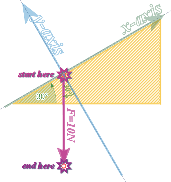
And, we need to either ‘move along \(x\) first, then move parallel to \(y\)’ OR ‘move along \(y\) first and then move parallel to \(x\)’
I used the 2nd one (moved along \(y\) first). Can you see why I did it that way? (It should be obvious):
The component along \(y\) is ‘adjacent’ to the angle, so: –10 sin 30 (it is negative, because it is pointing DOWN) = –5
The component parallel to \(x\) is ‘opposite’ the angle: –10 cos 30 (it is negative, because it is pointing LEFT) = –8.66
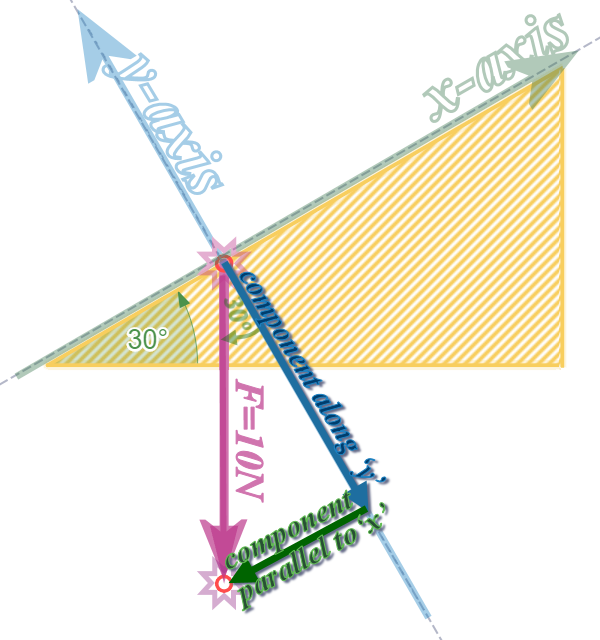
Perhaps this applet explains it better; but the applet won't remember to put the ‘SIGNS’ in, so watch out!
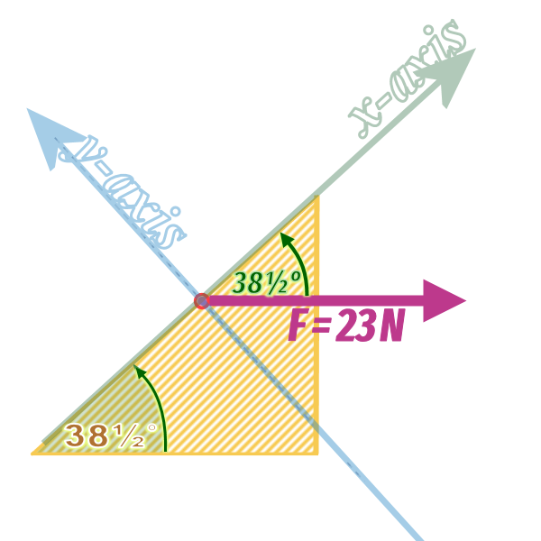
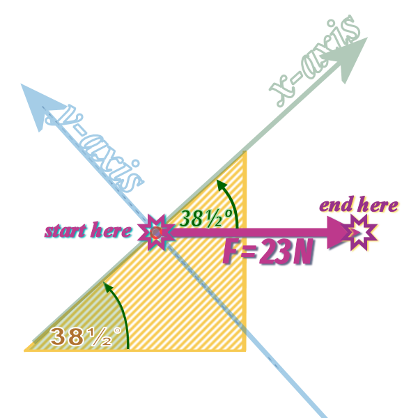
Question 1, part (b): We need to find the components of the \(23\) N force (which is acting rightwards)
Our components must be parallel to- and perpendicular to- the slope...
The first thing to do is to find the ANGLE between the \(25\) N force and one of our axes (either one...)
This rule will be helpful:
If the \(x\) axis is at \(\theta°\) to the horizontal, then the \(x\) axis is at \(\theta°\) to the horizontal! 🧐
├──────┬───────────┐
       │           ▼
       │
       │
       │
       │
       │
       │
       ▼
Now, we need to move from the start of the arrow (representing the \(23\) N force) to the end of the arrow :
And, we need to either ‘move along \(x\), then move parallel to \(y\)’ OR ‘move along \(y\) and then move parallel to \(x\)’
I used the 1st one (I moved along \(x\) first). Can you see why I did it that way? (It should be obvious):
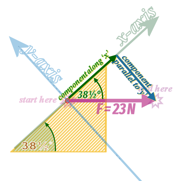
Here's an applet to help you visualise what we are trying to do:
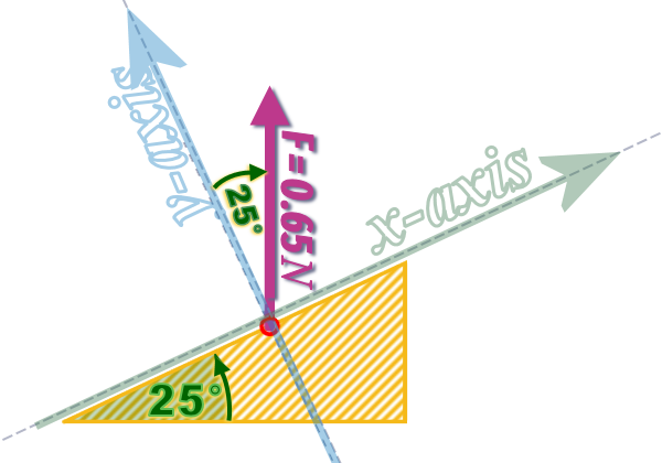
Question 1, part (c): You can use the \(Z\)-RULE to find the angle that the \(1.4\) N force makes with the slope...
(but it's still that same rule as in part (b):
So, in this question, the angle the \(x\) axis makes with ANY horizontal is \(50°\) ...)
The applet can show you how to resolve the force:
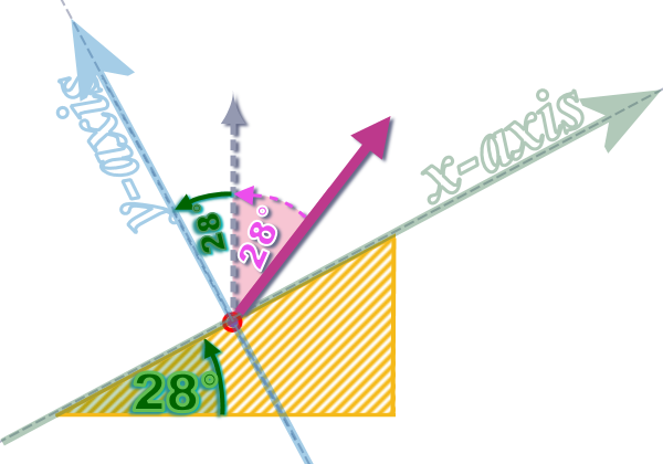
Question 1, part (d): We can make use of the rule:
If the \(x\) axis is at \(\theta°\) to the horizontal, then the \(y\) axis will be at \(\theta°\) to the vertical
                        ┌─►
So: we know this angle ├──┘
Therefore, it makes sense to ‘move along \(y\) and then move parallel to \(x\)’
Question 2, part (a): This should be easy for you now - but here's an applet in case you are stuck:
Question 3, part (a): We can make use of the rule:
If the \(x\) axis is at \(\theta°\) to the horizontal, then the \(y\) axis will be at \(\theta°\) to the vertical
So: we know this angle
        ┌─►
     ┌──┘
─────┘
Therefore, we know this angle:
I think you can take it from there....
Question 4:
Step 1: Draw a big, clear diagram with all of the forces shown:
So, our diagram looks like this:
The stone is sliding down the slope, but the only two forces acting on it:
- its weight and
- the reaction force
Step 2: Add in the x- and y-axes:
The \(x\) axis is placed along the slope...
...but in this case, I decided the axis heads down the slope (i.e. the same as the +VE direction)
Step 3: Resolve any forces which are not parallel to the axes:
Step 4: Decide which direction is +VE and then use: \(\begin{align} \color{#00ADB1}{\left( +VE\,forces \right)} \,&\color{#00ADB1}{-}\,\color{#00ADB1}{\left( -VE\,forces \right)} \,&\color{#00ADB1}{=\,ma}\\\left(\; mg\sin \left( 20° \right)\;\right)\, &- \,\left(\;\;\;0\;\;\; \right) \,&=\,ma\\& g\sin \left( 20° \right) \;\;\;&=\,a\\& 3.35 ms^{-2}\;&=\,a\end{align}\)
Interestingly: We weren't give the mass of the stone, but we were still able to calculate its acceleration down the slope - which tells us that the acceleration of a particle on a smooth slope depends only on the angle of the slope!
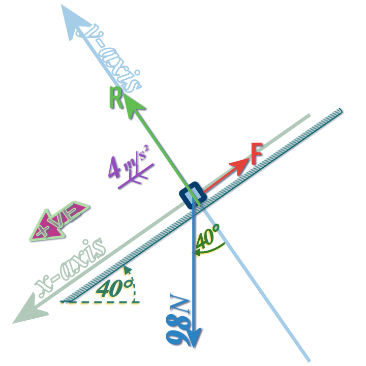
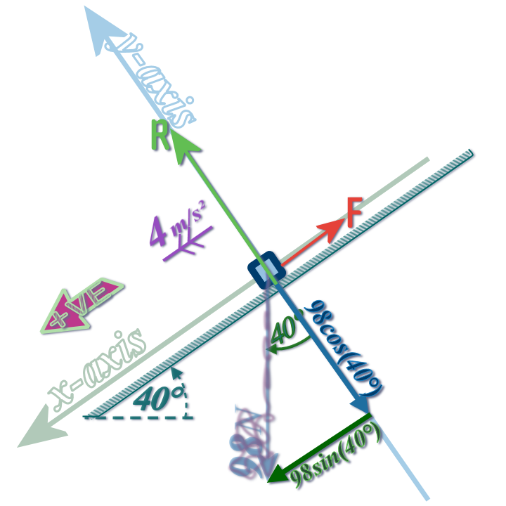
Question 5:
Step 1: Draw a big, clear diagram with all of the forces shown:
There are only TWO forces...
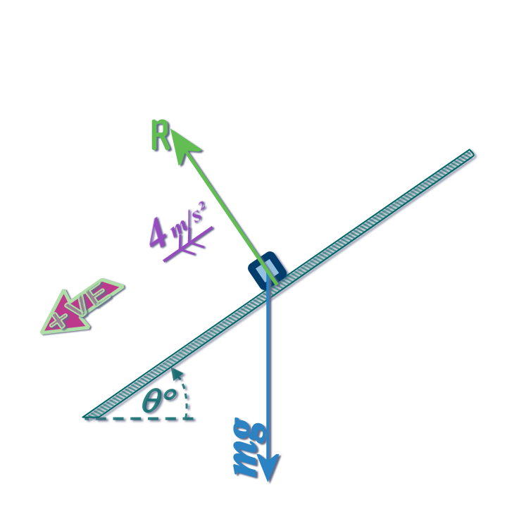
If the \(x\) axis is at \(\theta°\) to the horizontal, then the \(y\) axis will be at \(\theta°\) to the vertical
So we can replace the weight (\(mg\)) with these components:
Step 4: Decide which direction is +VE and then use: \(\begin{align} \color{#00ADB1}{\left( +VE\,forces \right)} \,&\color{#00ADB1}{-}\,\color{#00ADB1}{\left( -VE\,forces \right)} \,&\color{#00ADB1}{=\,ma}\\\left(\; mg\sin \left( \theta \right)\;\right)\, &- \,\left(\;\;\;0\;\;\; \right) \,&=\,m\left( 4 \right)\\& ........ \;\;\;&=\;...\\& \;\;\;\;\theta\;&=\;...°\end{align}\)
Interestingly: We weren't give the mass of the ball, but we were still able to calculate the angle of the slope from the acceleration - which tells us that the acceleration of a particle on a smooth slope depends only on the angle of the slope!
Question 6:
Step 1: Draw a big, clear diagram with all of the forces shown:
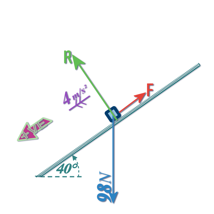
Step 2: Add in the x- and y-axes...
Step 3: Resolve any forces which are not parallel to the axes:
Step 4: Decide which direction is +VE and then use: \(\begin{align} \color{#00ADB1}{\left( +VE\,forces \right)} \,&\color{#00ADB1}{-}\,\color{#00ADB1}{\left( -VE\,forces \right)} \,&\color{#00ADB1}{=\,ma}\\\left(\; ...........\;\right)\, &- \,\left(\;\;\;F\;\;\; \right) \,&=\,\left( 10 \right)\left( 4 \right)\\& ........ \;\;\;&=\;...\\& \;\;\;\;F\;&=\;...N\end{align}\)
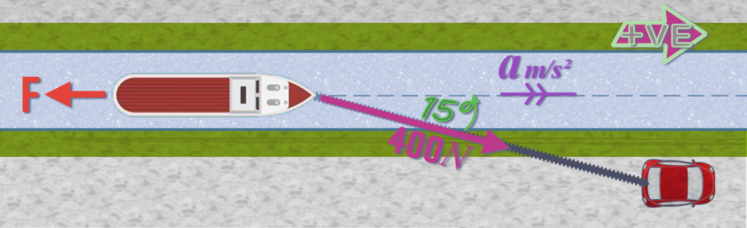
Question 7: These forces are not coplanar; so, to show it properly, I'd need to use a 3-D diagram of the situation:
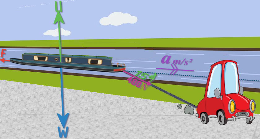
If the rope is horizontal (unlikely, but let's assume it is, because the angle of the rope to the horizontal is gonna be small; say 1-2°)...
...then the only vertical forces (or forces with any vertical component) are the weight and the upthrust...
Then, vertically, the weight and the upthrust must be equal...
...but if we simply ignore those, we can simplify this situation into an easy 2-D problem:
So here's the plan view:
Question 8, part (a): If the cyclist is travelling at ‘steady speed’, then we use: \(forces\,\,LEFT=forces\,\,RIGHT\):
Step 1: Draw a big, clear diagram with all of the forces shown:
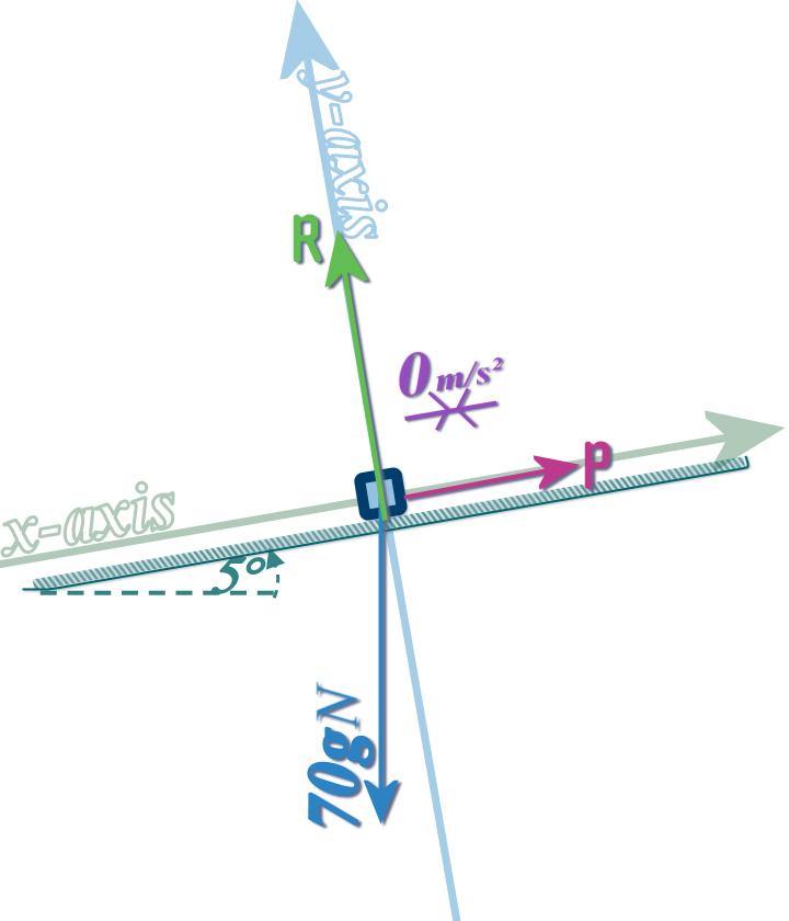
Step 2: Place an \(x\)-axis along the slope (and \(y\)-axis perpendicular to the slope) and resolve any oblique forces (that's just the weight) into components parallel to your axes:
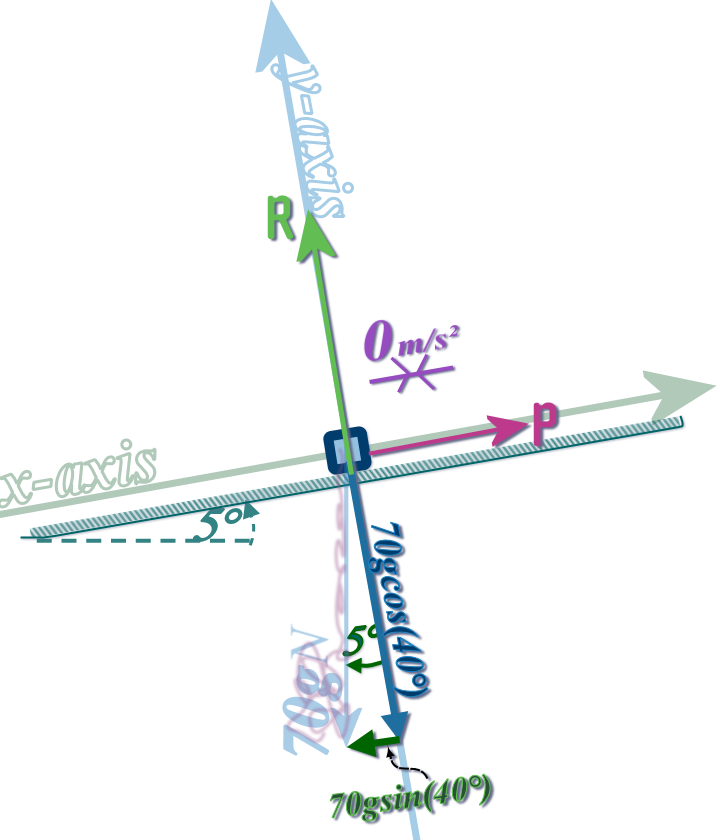
Step 3: For STATICS, use: \(forces\,\,LEFT=forces\,\,RIGHT\); for DYNAMICS use: \(\left( +VE\,\,forces \right) -\left( -VE\,\,forces \right) =ma\)
You decide!
Question 8, part (b): This time the acceleration is 1 m/s² upwards; but the diagram is still the same...
...although of course, it is now imperative that you decide a +VE direction (upwards seems obvious...)
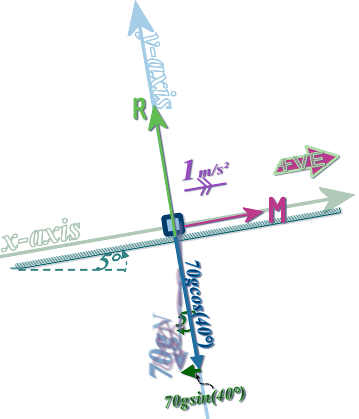
So, instead of using \(forces\,\,LEFT=forces\,\,RIGHT\); for DYNAMICS...
we'll use: \(\left( +VE\,\,forces \right) -\left( -VE\,\,forces \right) =ma\)
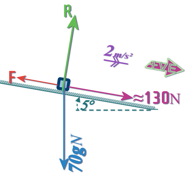
Question 8, part (c):
We need to use the cyclist's maximum force
(that we calculated in Part (b) )
Question 9:
MY DIAGRAM ON THE RIGHT IS WRONG! It's got a FORCE MISSING 🤥
So don't just copy it without thinking; you muppet!
Also the way I've drawn the reaction force might need explaining:
You know it has to act at \(90°\) to the surface (the ‘rod’)....
You can also see that the string is at \(25°\) to the rod, so it is pulling the bead slightly to the right?
But the bead is threaded onto the rod which only allows it to move vertically:
So, the rod must react with a force acting to the left...
...I mean, you can imagine pulling so hard that the rod starts to break free of its mounting: The top of the rod would move to the right, right? 🧐
So (until the rod moves) there must be a force stopping that from happening: The reaction force, which acts to the left....
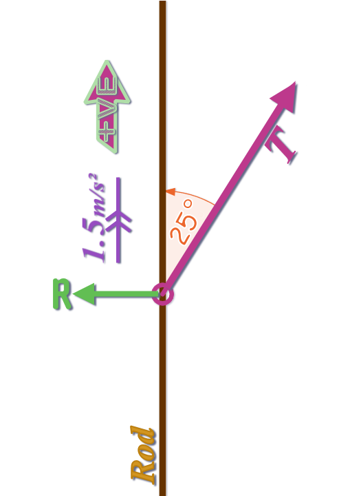
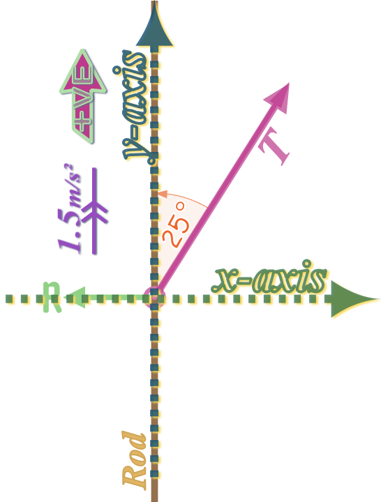
Then adding in the axes (normally, \(x\)-axis runs along the surface on which the motion takes place, but seeing as the motion is vertical, and that is already along \(y\), I just left the axes as they normally are...)
⟸ MY DIAGRAM STILL HAS A FORCE MISSING
Now resolve the forces and apply:
\(\left( +VE\,\,forces \right) -\left( -VE\,\,forces \right) =ma\)
Etc...
Question 10: Use a similar diagram to Question 7, except this time, the rope is at an angle of \(20°\) to the horizontal (so the forces are coplanar in this question)...
Question 12, part (a): They are simply asking us to explain the modelling assumptions that we use to simplify the situation and work out the answer...
The concrete slab is treated as a ‘particle’: Modelling an object as a ‘particle’ means we imagine it has no ‘dimensions’ and no ‘shape’ and that its mass is concentrated at a single point - therefore we can ignore rotational forces that might cause it to topple...
The slope is described as a ‘rough uniform surface’: That means that the slope is at the same angle to the horizontal at all points on the slope and that is there is friction between the slope and the particle
The motion is modelled as taking place along the line of greatest slope of the surface; which basically means the particle is pulled directly up the slope, not so that is traverses the slope...
The cable is modelled as ‘light’ and ‘inextensible’: ‘Light’ means we can ignore its weight. ‘Inextensible’ means that the cable doesn't stretch or undergo time dependent deformation
Question 12, part (b): In this question, the resistance to motion must be increasing at the speed increases:
So, firstly work out the resistance when the acceleration is \(\frac{1}{4}\) m/s²...
Then work out the resistance when the acceleration is \(0\) m/s² (i.e. it is moving at a steady speed of \(\frac{1}{2}\) m/s)